
Brief Introduction:
- Competitive and economical price with adjustable parameters.
- Surface mounted technology to improve the reliability of the circuit.
- We present industrial chips to meet industrial application temperature requirements.
- Optoelectronic isolation for analog voltage / PWM pulse / pulse frequency signal and other security interfaces.
- Super reliable design with safe forward and reverse, safe start, anti-interference, over temperature / over current/short circuit / under voltage / over voltage and other protections.
Definition of Part number:
BLSD | 24 | 10 | DC | 2Q | N | T | F | A | P |
BLDC drive | Rated Voltage | Peak current limit | DC input ① | Control mode | Parameter ② | Temp ③ | PG type ④ | Sensor type ⑤ | Speed regulation type ⑥ |
① : This code shows the DC Power input type of the drive: DC = Normal DC input; LDC = Ultra low voltage DC input; WDC = Wide range DC input; AC = AC input; ADC = AC and DC dual purpose.
② : This code shows the parameter type of the drive: N = Variable parameter; S = Simple fixed parameter; H = High current; SH = Small type high voltage; HV = High voltage.
③ : This code shows the temperature range of the drive: T = -40 ~ +65 ℃ , None = -10 ~ +45℃ .
④: This code shows the PG type: F = PG 1x hall sensor signal/phase, None= 6 x hall sensor signal/phase.
⑤ : This code shows the hall sensor degree of the drive: A = 60° Hall sensor, None = 120° Hall sensor.
⑥ : This code shows the speed regulation type: P = 0-3KHz speed regulation, None = voltage command.
Note: In order to let the part number easier to read, Some part number code will not be shown in the specification table, a code “X” will be instead. The full part number will be provided in the quotation or the proforma invoice…
Specifications:
| Model | Temp range (ºC) | Voltage range (VDC) | I-pk (A) | I-con (A) | 60º/120º Hall sensor | PWM f(kHz) | PI Close loop of speed | SV Ramp time (S) | SV Range (V) | LV /OV | Alm | PG | Heat Sink | Parameter Settings By Switch And Pot |
|---|---|---|---|---|---|---|---|---|---|---|---|---|---|---|
| BLSD1210DC-2Q-N-X | -10~+45 -40~+65 | 9~16 | 2.5~10 | 1.25~5 | √ | 15 | √ | 0.1/0.25 /0.5/1.0 | 0~5 | √ | √ | 24p@ 8-pole | X | √ |
| BLSD1220DC-2Q-N-X | -10~+45 -40~+65 | 9~16 | 5~20 | 2.5~10 | √ | 15 | √ | 0.1/0.25 /0.5/1.0 | 0~5 | √ | √ | 24p@ 8-pole | X | √ |
| BLSD1230DC-2Q-N-X | -10~+45 -40~+65 | 9~16 | 7.5~30 | 3.75~15 | √ | 15 | √ | 0.1/0.25 /0.5/1.0 | 0~5 | √ | √ | 24p@ 8-pole | X | √ |
| BLSD2410DC-2Q-N-X | -10~+45 -40~+65 | 17~32 | 2.5~10 | 1.25~5 | √ | 15 | √ | 0.1/0.25 /0.5/1.0 | 0~5 | √ | √ | 24p@ 8-pole | X | √ |
| BLSD2420DC-2Q-N-X | -10~+45 -40~+65 | 17~32 | 5~20 | 2.5~10 | √ | 15 | √ | 0.1/0.25 /0.5/1.0 | 0~5 | √ | √ | 24p@ 8-pole | X | √ |
| BLSD2430DC-2Q-N-X | -10~+45 -40~+65 | 17~32 | 7.5~30 | 3.75~15 | √ | 15 | √ | 0.1/0.25 /0.5/1.0 | 0~5 | √ | √ | 24p@ 8-pole | X | √ |
| BLSD3610DC-2Q-N-X | -10~+45 -40~+65 | 27~45 | 2.5~10 | 1.25~5 | √ | 15 | √ | 0.1/0.25 /0.5/1.0 | 0~5 | √ | √ | 24p@ 8-pole | X | √ |
| BLSD3620DC-2Q-N-X | -10~+45 -40~+65 | 27~45 | 5~20 | 2.5~10 | √ | 15 | √ | 0.1/0.25 /0.5/1.0 | 0~5 | √ | √ | 24p@ 8-pole | X | √ |
| BLSD3630DC-2Q-N-X | -10~+45 -40~+65 | 27~45 | 7.5~30 | 3.75~15 | √ | 15 | √ | 0.1/0.25 /0.5/1.0 | 0~5 | √ | √ | 24p@ 8-pole | X | √ |
| BLSD4810DC-2Q-N-X | -10~+45 -40~+65 | 37~55 | 2.5~10 | 1.25~5 | √ | 15 | √ | 0.1/0.25 /0.5/1.0 | 0~5 | √ | √ | 24p@ 8-pole | X | √ |
| BLSD4820DC-2Q-N-X | -10~+45 -40~+65 | 37~55 | 5~20 | 2.5~10 | √ | 15 | √ | 0.1/0.25 /0.5/1.0 | 0~5 | √ | √ | 24p@ 8-pole | X | √ |
| BLSD4830DC-2Q-N-X | -10~+45 -40~+65 | 37~55 | 7.5~30 | 3.75~15 | √ | 15 | √ | 0.1/0.25 /0.5/1.0 | 0~5 | √ | √ | 24p@ 8-pole | X | √ |
Technical Note:
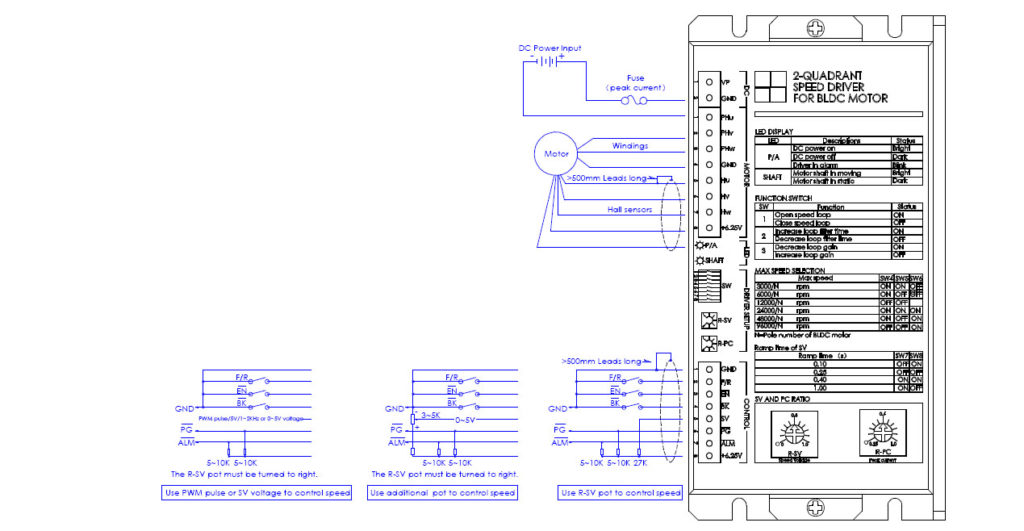
1.Control signals:
F/R—–H or Open=Forward, L or Close=Reverse
EN——H or Open=Disable, L or Close=Enable
BK——H or Open=Running, L or Close=Brake
SV——0~5V speed reference(112K input resistance)
PG—–Speed pulse output(OC)
ALM—Alarm output(OC)
2. Signal wire:
Control Signal cable and hall sensors cable can not be tied together with windings cable, otherwise, it will take interference. The long wire should be shielded wire.
3. Alarm conditions:
a. Hall sensor signals are not correct.
b. LV or OV for 1~3S.
c. Over temperature of case (80℃).
d. Over load for 5~6s continuously.
e. It can be reset by Turn-Off-On DC Power or Disable the driver once.
4. LED indicator:
P/A——-Bright=Driver is OK, Blink=Driver is in alarm
SHAFT—-Bright=Motor shaft is moving, Dark=Motor shaft is in static
5. Braking operation:
The motor speed must be less than the safe brake speed Ns when you brake the motor.
For Y windings, Ns=√3 x Ip x RL x N/ (2 x Vp)
For △windings, Ns=IP x RL x N/ (2 x √3 x Vp)
Ip=Peak current(A), RL=Line to line resistance of windings(Ohm)
N=No-load speed(rpm), Vp=Rated voltage(V), Ns=Safe brake speed(rpm)
6. Driver setup by pot and switch:
R-SV pot=SV voltage ratio, R-PC=Peak current ratio, SW1=Open/Close loop, SW2=Loop filter time, SW3=Loop gain, SW4,5,6=Speed range setting, SW7,8=SV ramp time setting
7. Peak current selection:
Ip>=2xIr or Ip>=4xPo/Vp, Ip is peak current of driver(A), Ir is rated current of motor(A), Po is rated output power of motor(W), Vp is rated voltage of driver(V)
Customization:
 |  |  |
| Heat sink | Motor tuning | Logo / brandmark |
- Heat Sink: Heat sink can be added according to customer request.
- Motor Tuning: Drivers can be tuned to fit the motors with different poles to match customer’s applications.
- Logo and brandmark: Customer’s Logo/brandmark can be printed on the frame of the driver according to the customer’s request.